2 चॅनल रीलेला आरडूइनो वापरून कसे कंट्रोल करतात
आज आपण 2 चॅॅनल रिलेला आरडूइनो वापरून कसे कंट्रोल करता येते हे पाहू.
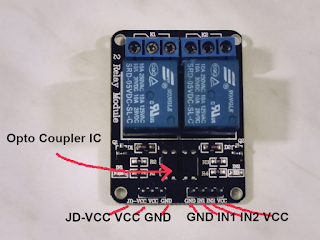
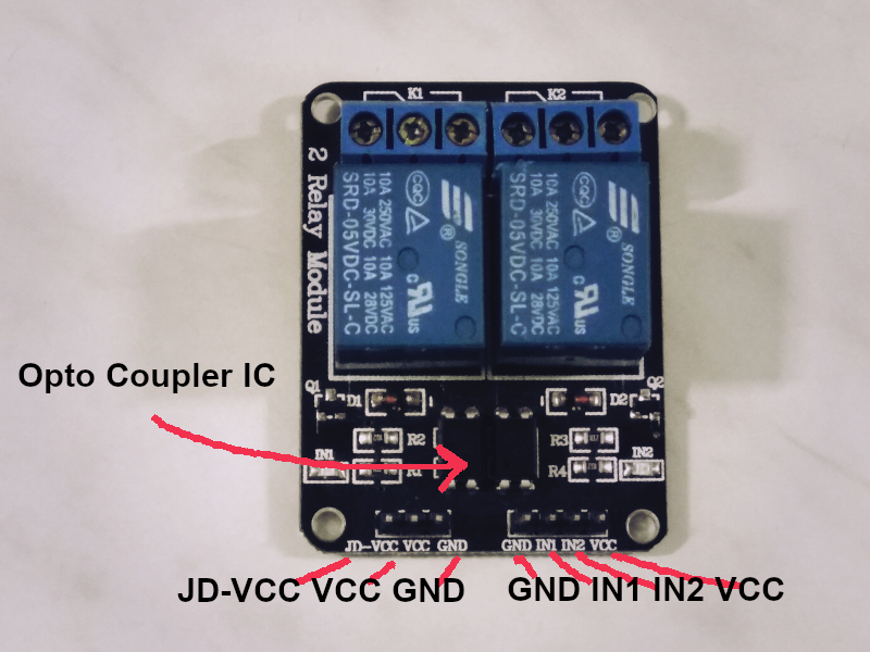
वरील फोटो मध्ये दिसणारा 2 चॅॅनल ऑप्टो कपलर रिले मी अमॅॅझॉॉन इंडिया वर विकत घेतला आहे. हा एक 5v चा रिले आहे. याला ऑपरेट करण्यासाठी 5 वोल्ट ची गरज असते. हा सप्लाय रिलेला दोन वेगवेगळ्या ठिकाणी द्यावा लागतो. VCC आणि GND ला व JD-VCCआणि GND ला.
या रिले मध्ये ऑप्टो कप्लर किंवा ऑप्टो आइसोलेटरचे IC आणि सर्किट दिसते. यात आपण दोन वेगवेगळे सर्किट ओळखू शकतो. या दोन्ही मध्ये जोडणारे इलेक्ट्रिक कनेक्शन नसते. तर अशा रीतीने ऑप्टो कप्लर काम करतो. .
जेव्हा तुम्ही नवीन रीले विकत घेता तेव्हा त्यात VCC आणि JD-VCC वर एक जम्पर पिन जोडलेली तुम्हाला दिसून येते. यामुळे VCC ला दिलेला सप्लाय JD-VCC मधून दुसऱ्या सर्किटला पण मिळतो. पण यामुळे ऑप्टो आइसोलेशन घडून येत नाही. याचा वापर रीले ठीक ठाक काम करत आहे का हे चेक करण्यासाठी होऊ शकतो, पण रीलेच्या आउटपुटला AC किंवा DC लोड जोडायचा असेल तर ही जम्पर ची पिन काढून टाकली पाहिजे, आणि VCC - GND ला 5v चा वेगळा सप्लाय दिला पाहिजे.

या ठिकाणी एका गोष्टीची काळजी घ्यावी लागते ते म्हणजे जम्पर पिनला कधीही VCC-GND शी जोडू नये. असे केल्यास शॉर्ट सर्किट होऊन रिले आणि आरडूइनो चा बोर्ड दोन्हीही निकामी होऊ शकतात.
आता या प्रयोगात वापरलेले साहित्य पाहू

Arduino Uno, केबल, काही मेल - फिमेल जम्पर वायर्स , 2 चॅॅनलचा रिले (5 v) , एक ब्रेड बोर्ड पॉवर सप्लाय, 12 वोल्ट चा dc अडाप्टर.
याची वायरिंग समजण्यासाठी खाली मी एक ड्रॉइंग बनवले आहे

Arduino च्या 5v आणि ग्राउंडला रीलेच्या VCC आणि ग्राउंडला जोडा
ब्रेड बोर्ड पॉवर सप्लाय पासून रीलेच्या JD-VCC आणि ग्राउंडला (जम्पर काढून) 5 वोल्ट चा सप्लाय द्या.
आता आरडूइनोच्या पिन क्र 7 आणि 8 ला रिलेच्या IN1 आणि IN2 शी जोडा.
शक्य असेल तर कलर कोड वापरा. मी पॉजिटिव सप्लाई साठी लाल, ग्राउंड साठी काळी आणि सिग्नल साठी पिवळ्या रंगाच्या वायरचा वापर केला आहे.
आता dc अडाप्टरला ब्रेड बोर्ड पॉवर सप्लाय मोड्यूलशी जोडा आणि आरडूइनो ला कॉम्प्युटरशी. आता आरडूइनोचे सोफ्टवेअर ओपन करा. या प्रयोगासाठी लागणारा प्रोग्राममी खाली समजावून सांगितला आहे. तसेच शेवटी डाउनलोड लिंकपण दिली आहे. कृपया प्रोग्रामिंगला इंग्रजीतच समजावून घ्याल तर बरे होईल .
These are the variables that you declare at the beginning of the program. Relay1, Relay2 are variables. And 7 and 8 are the port number or pin numbers on Arduino Uno which we will be using to connect to the IN1 and IN2 of the relay module.
int Relay1 = 7;
int Relay2 = 8;
This is the setup() function of the Arduino. Whatever code you write here will be executed once in the beginning when the program runs. After that only the code in the loop() function will run over and over again till you disconnect the power supply of the Arduino. The program will resume as soon as you power the Arduino again.
The Serial.begin(9600) function opens the serial port and sets data rate to 9600 bps. We will be opening the Serial communication only if we need to check the output on the connected computer. If you intend to run this program without connecting to the computer, after the program and the circuit are tested. You can reduce the overhead by commenting out all the lines that begin with "Serial."
You do not need Serial () functions to be consuming your processing power if you are not looking at the output on the Serial Monitor a computer.
There is more to understand here. We will go into it in a later article.
We declare the pins, that is the Variables Relay1 and Relay2 to be outputs. Then immediately we turn them High. When we turn a pin HIGH using the digitalWrite() function, the LED is turned on if connected with that port, but that is not the case with our relays. We are using Active Low type of relays. And we will turn then Off, to do that we neeed to send HIGH on the port.
void setup() {
Serial.begin(9600);
pinMode(Relay1, OUTPUT);
pinMode(Relay2, OUTPUT);
digitalWrite(Relay1, HIGH);
digitalWrite(Relay2, HIGH);
}
Now we come to the loop() function. Whatever code we write in this function runs over and over again till the Arduino has power. Now we will Turn the Relay On for 1 second one after the other and then turn them off in the reverse order. You can notice the LEDs of the corresponding Relays turned on and the Clicking sound of the Relays as they take their turns.
void loop() {
digitalWrite(Relay1, LOW);
Serial.println("Relay 1 On");
delay(1000);
digitalWrite(Relay2, LOW);
Serial.println("Relay 2 On");
delay(1000);
digitalWrite(Relay2, HIGH);
Serial.println("Relay 2 Off");
delay(1000);
digitalWrite(Relay1, HIGH);
Serial.println("Relay 1 Off");
delay(1000);
}
प्रयोग करताना लहान लहान चुकामुळे प्रयोग पूर्ण होत नाही. या चुका जर पटकन लक्षात आल्या तर ते दूर करून प्रयोग पटकन पूर्ण करता येतो. अशाच एका चुकीचे GIF तुम्हाला खाली दिसून येते.

या प्रयोगात रीलेच्या दोन्ही एलईडी प्रोग्राम प्रमाणे जळता विझताना दिसतात, पण रीलेचा आवाज ऐकू येत नाही. जर प्रयोग करताना अशी स्थिती निर्माण झाली तर ब्रेड बोर्ड पॉवर सप्लाय हून JD-VCC आणि GND ला जोडणाऱ्या वायरी एक तर नीट जोडल्या गेल्या नाहीत किंवा त्या खराब आहेत असे समजावे.
वरील फोटो मध्ये दिसणारा 2 चॅॅनल ऑप्टो कपलर रिले मी अमॅॅझॉॉन इंडिया वर विकत घेतला आहे. हा एक 5v चा रिले आहे. याला ऑपरेट करण्यासाठी 5 वोल्ट ची गरज असते. हा सप्लाय रिलेला दोन वेगवेगळ्या ठिकाणी द्यावा लागतो. VCC आणि GND ला व JD-VCCआणि GND ला.
या रिले मध्ये ऑप्टो कप्लर किंवा ऑप्टो आइसोलेटरचे IC आणि सर्किट दिसते. यात आपण दोन वेगवेगळे सर्किट ओळखू शकतो. या दोन्ही मध्ये जोडणारे इलेक्ट्रिक कनेक्शन नसते. तर अशा रीतीने ऑप्टो कप्लर काम करतो. .
जेव्हा तुम्ही नवीन रीले विकत घेता तेव्हा त्यात VCC आणि JD-VCC वर एक जम्पर पिन जोडलेली तुम्हाला दिसून येते. यामुळे VCC ला दिलेला सप्लाय JD-VCC मधून दुसऱ्या सर्किटला पण मिळतो. पण यामुळे ऑप्टो आइसोलेशन घडून येत नाही. याचा वापर रीले ठीक ठाक काम करत आहे का हे चेक करण्यासाठी होऊ शकतो, पण रीलेच्या आउटपुटला AC किंवा DC लोड जोडायचा असेल तर ही जम्पर ची पिन काढून टाकली पाहिजे, आणि VCC - GND ला 5v चा वेगळा सप्लाय दिला पाहिजे.

या ठिकाणी एका गोष्टीची काळजी घ्यावी लागते ते म्हणजे जम्पर पिनला कधीही VCC-GND शी जोडू नये. असे केल्यास शॉर्ट सर्किट होऊन रिले आणि आरडूइनो चा बोर्ड दोन्हीही निकामी होऊ शकतात.
आता या प्रयोगात वापरलेले साहित्य पाहू

Arduino Uno, केबल, काही मेल - फिमेल जम्पर वायर्स , 2 चॅॅनलचा रिले (5 v) , एक ब्रेड बोर्ड पॉवर सप्लाय, 12 वोल्ट चा dc अडाप्टर.
याची वायरिंग समजण्यासाठी खाली मी एक ड्रॉइंग बनवले आहे

Arduino च्या 5v आणि ग्राउंडला रीलेच्या VCC आणि ग्राउंडला जोडा
ब्रेड बोर्ड पॉवर सप्लाय पासून रीलेच्या JD-VCC आणि ग्राउंडला (जम्पर काढून) 5 वोल्ट चा सप्लाय द्या.
आता आरडूइनोच्या पिन क्र 7 आणि 8 ला रिलेच्या IN1 आणि IN2 शी जोडा.
शक्य असेल तर कलर कोड वापरा. मी पॉजिटिव सप्लाई साठी लाल, ग्राउंड साठी काळी आणि सिग्नल साठी पिवळ्या रंगाच्या वायरचा वापर केला आहे.
आता dc अडाप्टरला ब्रेड बोर्ड पॉवर सप्लाय मोड्यूलशी जोडा आणि आरडूइनो ला कॉम्प्युटरशी. आता आरडूइनोचे सोफ्टवेअर ओपन करा. या प्रयोगासाठी लागणारा प्रोग्राममी खाली समजावून सांगितला आहे. तसेच शेवटी डाउनलोड लिंकपण दिली आहे. कृपया प्रोग्रामिंगला इंग्रजीतच समजावून घ्याल तर बरे होईल .
These are the variables that you declare at the beginning of the program. Relay1, Relay2 are variables. And 7 and 8 are the port number or pin numbers on Arduino Uno which we will be using to connect to the IN1 and IN2 of the relay module.
int Relay1 = 7;
int Relay2 = 8;
This is the setup() function of the Arduino. Whatever code you write here will be executed once in the beginning when the program runs. After that only the code in the loop() function will run over and over again till you disconnect the power supply of the Arduino. The program will resume as soon as you power the Arduino again.
The Serial.begin(9600) function opens the serial port and sets data rate to 9600 bps. We will be opening the Serial communication only if we need to check the output on the connected computer. If you intend to run this program without connecting to the computer, after the program and the circuit are tested. You can reduce the overhead by commenting out all the lines that begin with "Serial."
You do not need Serial () functions to be consuming your processing power if you are not looking at the output on the Serial Monitor a computer.
There is more to understand here. We will go into it in a later article.
We declare the pins, that is the Variables Relay1 and Relay2 to be outputs. Then immediately we turn them High. When we turn a pin HIGH using the digitalWrite() function, the LED is turned on if connected with that port, but that is not the case with our relays. We are using Active Low type of relays. And we will turn then Off, to do that we neeed to send HIGH on the port.
void setup() {
Serial.begin(9600);
pinMode(Relay1, OUTPUT);
pinMode(Relay2, OUTPUT);
digitalWrite(Relay1, HIGH);
digitalWrite(Relay2, HIGH);
}
Now we come to the loop() function. Whatever code we write in this function runs over and over again till the Arduino has power. Now we will Turn the Relay On for 1 second one after the other and then turn them off in the reverse order. You can notice the LEDs of the corresponding Relays turned on and the Clicking sound of the Relays as they take their turns.
void loop() {
digitalWrite(Relay1, LOW);
Serial.println("Relay 1 On");
delay(1000);
digitalWrite(Relay2, LOW);
Serial.println("Relay 2 On");
delay(1000);
digitalWrite(Relay2, HIGH);
Serial.println("Relay 2 Off");
delay(1000);
digitalWrite(Relay1, HIGH);
Serial.println("Relay 1 Off");
delay(1000);
}
प्रयोग करताना लहान लहान चुकामुळे प्रयोग पूर्ण होत नाही. या चुका जर पटकन लक्षात आल्या तर ते दूर करून प्रयोग पटकन पूर्ण करता येतो. अशाच एका चुकीचे GIF तुम्हाला खाली दिसून येते.
या प्रयोगात रीलेच्या दोन्ही एलईडी प्रोग्राम प्रमाणे जळता विझताना दिसतात, पण रीलेचा आवाज ऐकू येत नाही. जर प्रयोग करताना अशी स्थिती निर्माण झाली तर ब्रेड बोर्ड पॉवर सप्लाय हून JD-VCC आणि GND ला जोडणाऱ्या वायरी एक तर नीट जोडल्या गेल्या नाहीत किंवा त्या खराब आहेत असे समजावे.
टिप्पण्या
टिप्पणी पोस्ट करा